The basic physical relationships for the formation of induced eddy currents that generate heat in a conducting material are explained. In addition, the structural elements of induction coils, their function in heating the charge, formulas for designing coil parameters, and brief operational aspects of induction melting furnaces are described.
Induction
Introduction Induction heating of metallic materials using the principle of electromagnetic induction is currently widely used, especially in the foundry industry. The main advantages of this technology are high energy efficiency, a clean working environment without direct contact with the heated charge and very precise control of the heating process. The principle consists in the conversion of electrical energy into thermal energy through wireless transmission by electromagnetic induction, without any direct losses.
Electromagnetic induction
According to Faraday's law of electromagnetic induction, a closed conducting circuit subjected to changes in magnetic flux Φ induces an electric voltage e proportional to the rate of change of this flux:
e = -N * dΦ/dt (1)
where N is the number of turns surrounding the magnetic flux Φ.
This induced electromotive voltage e gives rise to eddy currents (also called Foucault currents) closing in the conducting material perpendicular to the direction of the magnetic flux. The magnitude of these eddy currents I induced in the metallic material can be determined from the relation:I = σ * B * S * ω / ρ (2)
where σ is the specific electrical conductivity of the material, B is the magnetic induction, S is the cross-sectional area of the material perpendicular to the B direction, ω is the angular rate of change of the magnetic field, and ρ is the specific resistance of the material
Flowing eddy currents I induced in a metallic material produce heat losses P proportional to the square of their current density:
P = I^2 * R = (σBS*ω)^2 * ρ / V (3)
where R is the resistance of the material and V its volume. In this non-contact way, energy can be efficiently transferred to the conductive material for heating and eventual melting.
Induction coil
The key element of induction melting furnaces using electromagnetic induction is the induction coil (inductor). Its function is to create a variable magnetic field of sufficient intensity in its surroundings to induce the desired eddy currents and the heat generated by them in the metallic material of the insert.
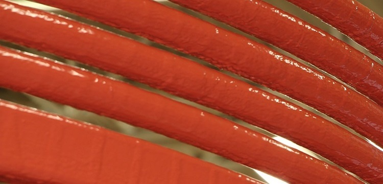
Induction coils are typically constructed as windings of copper tubing that allow internal intense water cooling. Suitable coil shapes for various applications are circular or square loops, or shaped coils according to the desired insert shape. Copper conductors must be of sufficient cross-section to carry large currents up to hundreds of kA.
The number of turns N and the cross section S of the coil shall be designed to achieve the required magnetic induction B for the effective induction of eddy currents in the charge according to equations (1) and (2). The coil impedance Z should then be as low as possible to limit losses during high frequency operation at typical frequencies of 50 Hz - 10 kHz. The power transfer efficiency η can be expressed as the ratio of the input power P in the load to the input power PZ on the coil:
η = P/PZ = P/(I^2*Z) (4)
where I is the effective current flowing through the coil, which increases the losses in the copper winding proportional to the square of. Thus, the input power PZ on the coil must be sufficient to cover the required input power P in the load (according to Equation 3) and sufficient margin to compensate for losses in the copper.
Coil function during melting
In an induction melting furnace, the coil is placed around a refractory crucible containing a metal insert to be melted. When the coil is connected to an alternating current of a suitable frequency, a variable magnetic field is generated in its windings, which induces eddy currents in the conductive charge.
These induced eddy currents IV in the charge generate Joule losses PV proportional to the square of their current density JV2 according to relation (3):PV = JV2 * ρ * V (5)
These losses, in the form of heat, are evenly distributed over the entire volume of the insert. This ensures that the entire volume of metal is evenly heated and gradually completely melted without localised hot spots.
In addition, the movement of charged particles of electric currents inside the conductive material of the charge and the mutual interaction of their magnetic fields cause electromagnetic swirling and intense mixing of the melt. This helps to homogenize the molten metal.
The heating rate and time required to melt a charge of a given type and volume depends on the induced PV power proportional to (5) the magnetic field strength of the coil, the conductivity and the volume of the charge. By optimizing the induction coil parameters and adjusting the power, the melting process can be precisely controlled.
Induction melting furnace
The main structural elements of an induction melting furnace are the refractory crucible, the induction coil, the water cooling system, the cladding, and the supply cables for connecting the high-frequency current.
The insert is placed in a refractory crucible that is lined with refractory materials such as refractory fireclay or corundum bricks and masses. This lining forms thermal insulation while resisting the effects of high temperatures, the chemical effects of molten metals, and oxidizing flames.
Around the crucible is a close-fitting induction coil that creates a variable electromagnetic field to heat the charge. The coil is wound from hollow copper tubing through which cooling water flows and is discharged to an external water cooling circuit. Adequate and uniform internal cooling of the coil is essential to maintain its longevity when operating in highly thermally and electrically stressed environments.
The furnace is also equipped with monitoring and control elements such as temperature gauges, power regulators, controls for frequency adjustment and control of the coil position relative to the load. The outer cladding also provides a solid structure to the furnace, mechanical protection and shielding to the operating personnel from strong electromagnetic fields during operation.
Operation and Maintenance
The operation of induction furnaces also imposes some specific requirements, in particular to maintain the functionality and lifetime of the induction coil as one of the most stressed components. High molten metal temperatures and extreme heat loads cause significant thermal stress on the copper conductors and gradual degradation of the coil insulation layers. In addition, large current flows generate significant electromagnetic forces acting on the windings and increasing mechanical stresses. For these reasons, induction coils generally have a limited lifetime of a few hundred to thousands of fusion cycles. However, by proper operation and preventive maintenance, this lifetime can be significantly extended. This includes, but is not limited to, regular checking of the insulation condition, timely replacement of defective coils, checking for tight winding attachment and sufficient cooling.Other operational risks are related to the handling of molten metals, where possible inexpert handling can result in chemical or thermal damage. It is therefore essential to ensure appropriate safety and fire precautions around induction furnaces.
Conclusion
The principle of electromagnetic induction finds a very effective application in the field of induction melting and processing of metallic materials, especially in the foundry industry. The use of induction coils for non-contact energy transfer to the charge ensures fast and uniform heating of the entire volume of material without undesirable effects such as the formation of oxide layers, local overheating or contamination of the melt.
The main advantages of this technology include high efficiency of electrical to thermal energy conversion, better process controllability and a clean working environment without flue gas contamination. By selecting the appropriate furnace design and parameters, the power, time and temperature of the melting process can be adjusted with high precision for various metallic materials such as cast iron, steel, aluminum, copper alloys, zinc and other non-ferrous metals.
Induction melting furnaces thus represent a promising equipment for modern foundry production. Further developments in this field are aimed at extending the service life of furnace components, increasing efficiency and developing new types of coils tailored to specific applications.
Reference:
[1] LUKEŽIČ, V. Induction and dielectric furnaces. Prague: SNTL, 1962.
[2] KAWECKI, M. Energy analysis of induction melting in foundry. Archives of Foundry Engineering, 2012, vol. 12, no. 4.
[3] ULEWICZ, R. and PRIERSON, J. "Investigation of cunsability of cooling systems of coils in induction furnaces." Manufacturing Technology, 2013, vol. 13, no. 4.
[4] BOCA, M., GASIOR, P., SZLIGA, D. Electromagnetic and heat flow simulation for coreless induction furnace. Archives of Metallurgy and Materials, 2015, vol. 60, no. 2.


